Welding Symbols Chart Printable Welding table, Welding projects, Welding

[DIAGRAM] Ultrasonic Welding Diagram
Each common type of weld is represented by its own unique symbol on a weld symbol chart. Learning to correctly identify each weld is important for understanding welding symbols. Reference Line. The reference line is a single horizontal line which serves as the foundation for the rest of the welding symbol. The reference line itself does not.

Welding Blueprints 101 How To Read Them
Most of the common weld types in the industry are used when the joint has two members joining together to create an intersection of 90 degrees. Although you can apply it at different angles, it would be more prominent at 90 degrees. You can use a fillet weld symbol above or below the reference line or on both sides.
Weld Symbols Chart American Welding Society DWG file Autodesk_AutoCAD
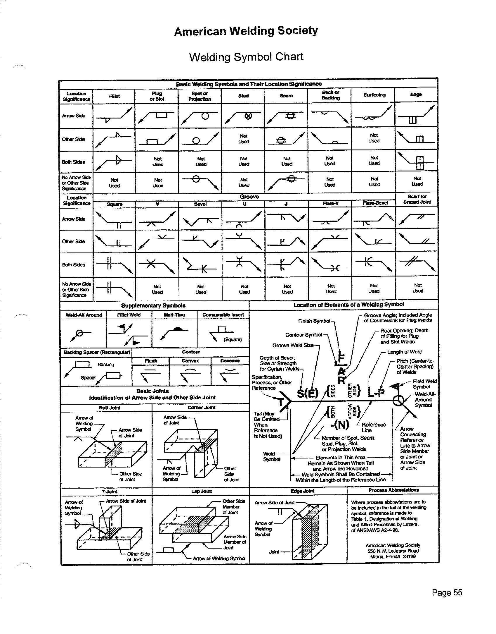
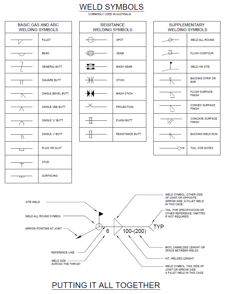
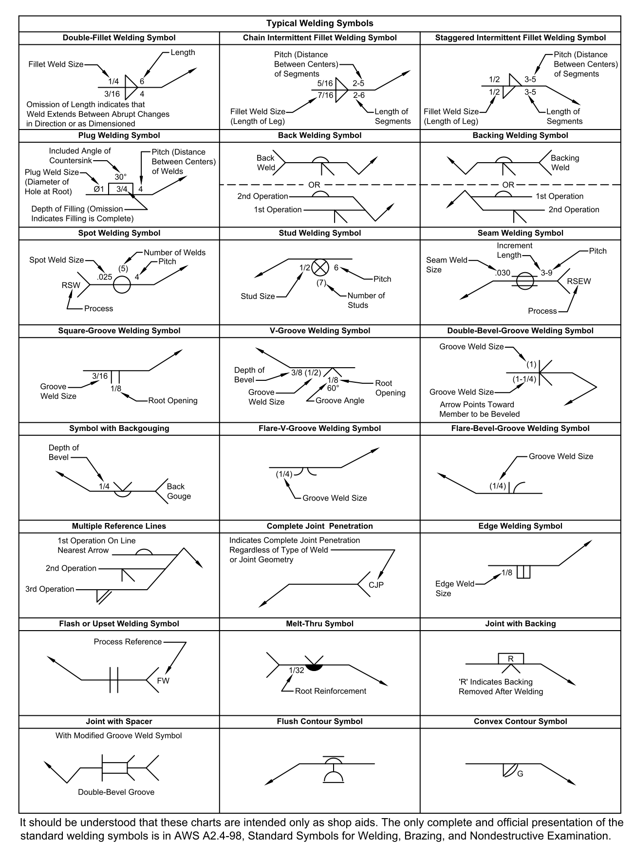
What is drawn? A chart of the basic welding symbols and their location significance. A chart of the supplementary symbols. A drawing of the location of elements of a welding symbol and how to put it all together. Isometric views of basic joints identification of arrow side and other side joint examples. Typical welding symbols examples.
Welding Symbols Mechanical Tips Electrical & Mechanical Engineering
Updated January 4, 2024 The easy way to learn welding symbols. When you are welding, you need clear instructions, and that's where the welding symbol gives that clarity. It is a directive, telling you exactly what type and technique the welder should employ. Weld symbols can be complicated to understand, so here are the basics of how to read them.
Direction of the field weld symbol
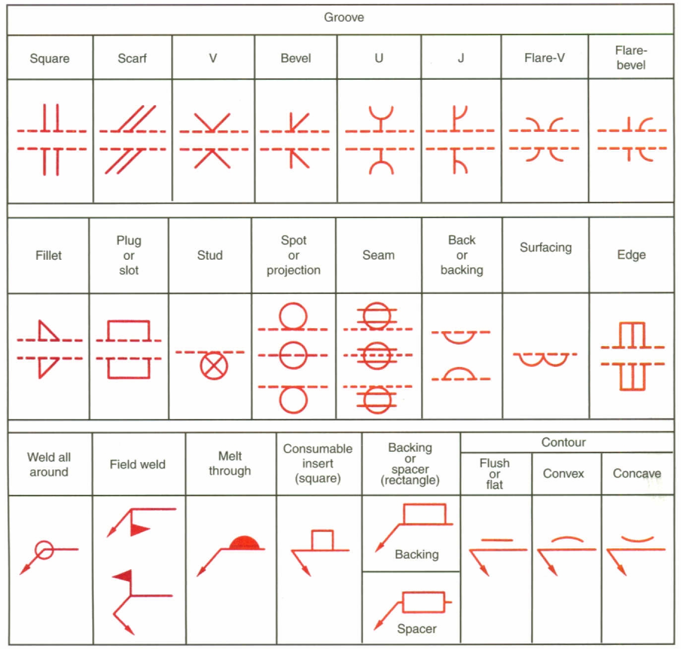
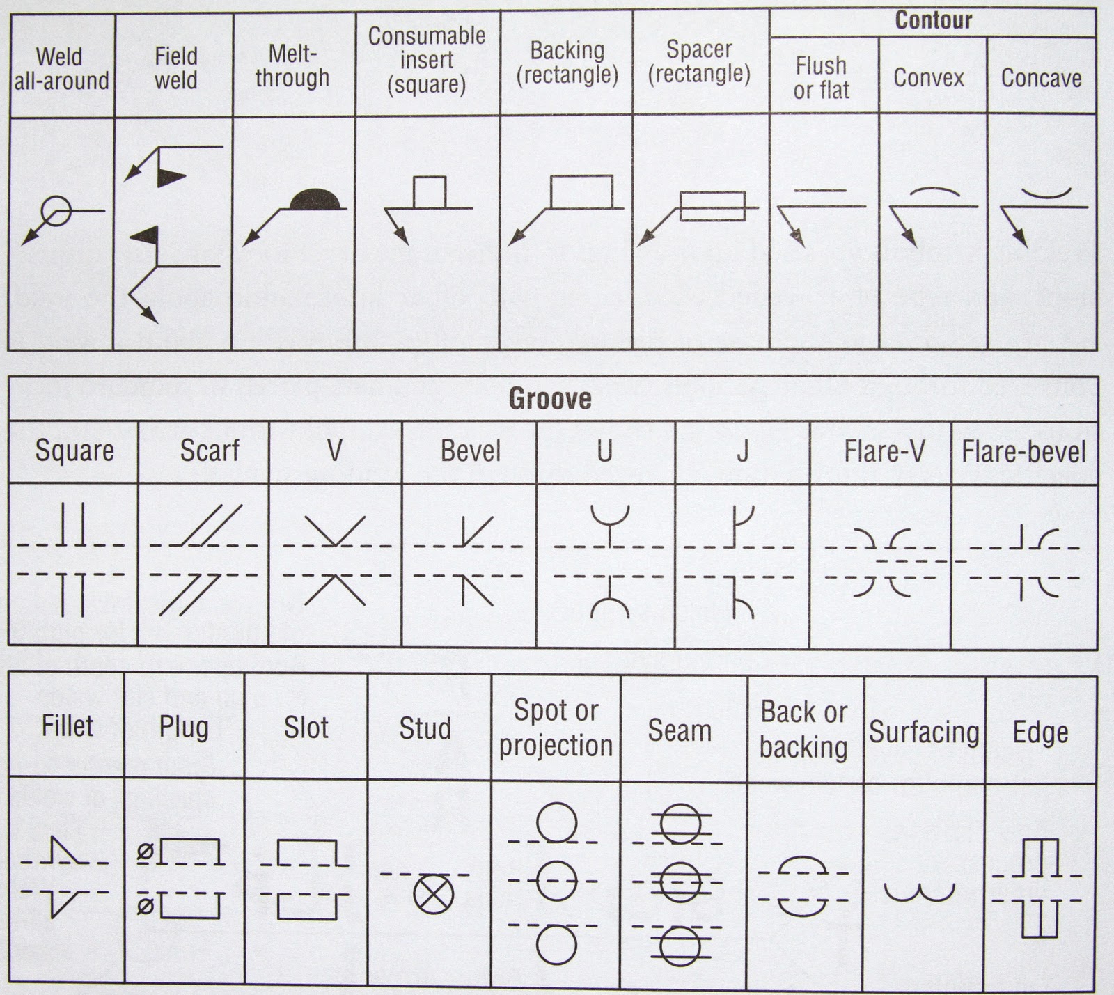
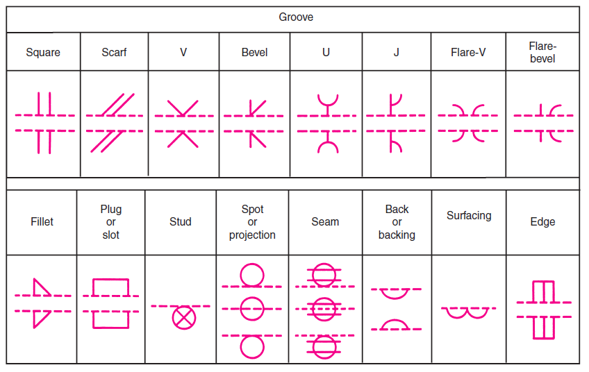
Common Weld Symbols The table presents some of the most commonly used welding symbols. Fillet - The most used weld. Groove - Second most used. It usually involves preparing the edge pieces to form one of the groove weld shapes like V, bevel, U, J, Flare V, Flare bevel or no preparation at all with square edges to form a square groove.
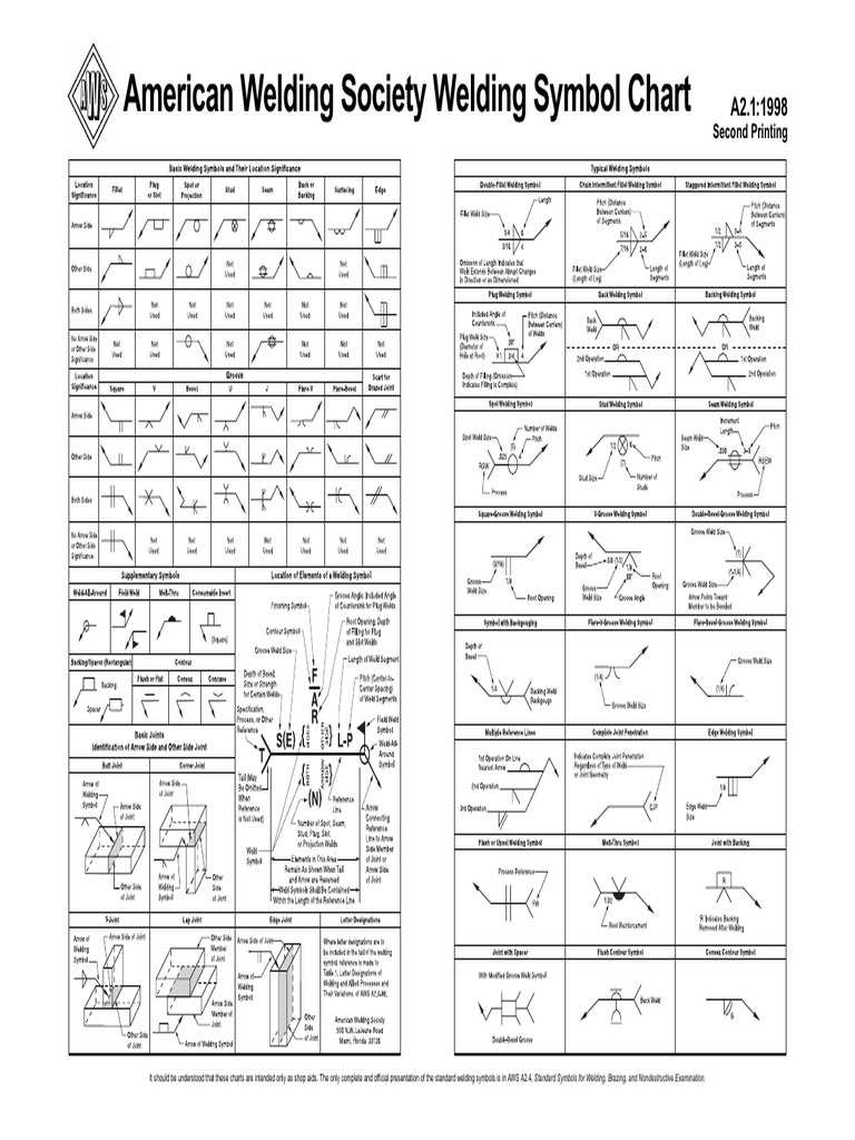
AWS A2.1 Welding Symbol Chart.pdf
August 11, 2022 When you see an engineering fabrication drawing, you will notice several welding symbols on the drawing. Weld symbols and welding symbols enable the designer to communicate and convey the required welding details to the fabricator.
Basic Welding Symbols Weld My World
Created Date: 1/13/2012 8:35:12 AM
Easy Guide to Welding Symbols
ˇˆ˙ˇ˝ ˛˚ ˘ ˇ ˆ ˙ ˘ ˇˇˆ. Title: A21-desk.fm Author: Default Created Date: 7/25/2001 8:48:45 AM
Understanding the Welding Symbols [Explained with Diagrams] cruxweld
Welding Symbols Explained: Complete List with Diagrams November 22, 2023 / By Shane / 13 minutes of reading Table of Contents 1. Scope This standard outlines the method of presenting welding symbols. It is applicable to both metal fusion welding and resistance welding. 2. Normative References
Structural Drafter
The weld symbol distinguishes between the two sides by using the arrow and the spaces above and below the reference line. The side of the joint to which the arrow points is known as the arrow side, and that weld's instructions are given below the reference line.
Welding Symbol Examples Welding
The weld symbol is the little icon that is drawn on the reference line of the welding symbol. It indicates the desired type of weld. The welding symbol is the whole thing, weld symbol and all. The assembled "welding symbol" consists of the following eight elements, or any of these elements as necessary: reference line, arrow, basic weld.

Welding Symbols Chart Printable Welding table, Welding projects, Welding
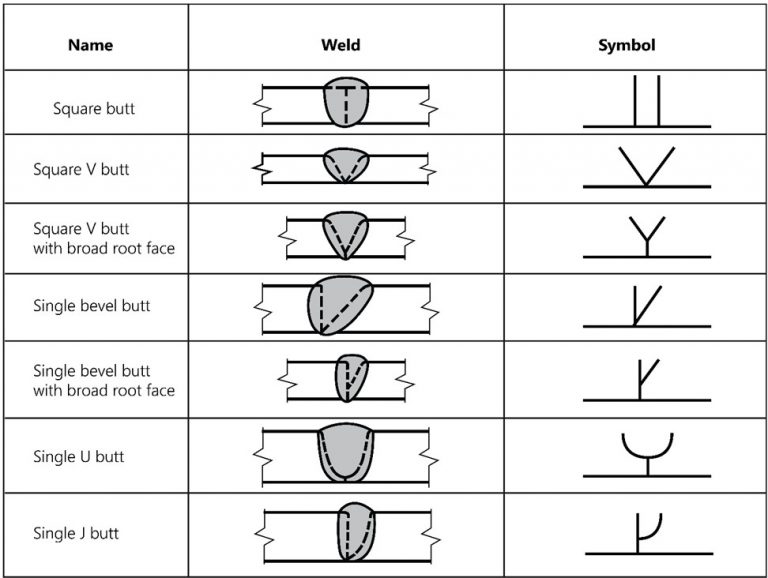
An Explanation of the Basic Welding Symbols (With Charts) - Google Docs Square butt Square V butt Square V butt with broad root face Single bevel butt Single bevel butt with broad root face Single U butt Single J butt Symbol Name Double sided V butt Double sided bevel butt Double sided U butt weld Symbol

Welding Symbols & their description MADLAB ENGINEERING
The welding symbols are illustrations of the pre-weld joint looking side on, as through a cross-section. Each weld symbol is explained individually, with its weld profile alongside it.
Welding Symbols Chart Printable
AWS A2.0 was first published in 1947 and was revised in 1958 and 1968. AWS A2.2 first appeared in 1958 and was revised in 1969. The evolution of AWS A2.4, Standard Symbols for Welding, Brazing, and Nondestructive Testing, is shown below: ANSI/AWS A2.4-76. Symbols for Welding and Nondestructive Testing;

Pin on Welded table
The most common groove weld symbol encountered is the bevel weld symbol, which can be broken down into a single bevel, or a double bevel which is also known as a V-Groove. When referring to the Basic Weld Symbols chart, note the different potential groove geometries and their visual representation of them. Other Weld Symbols
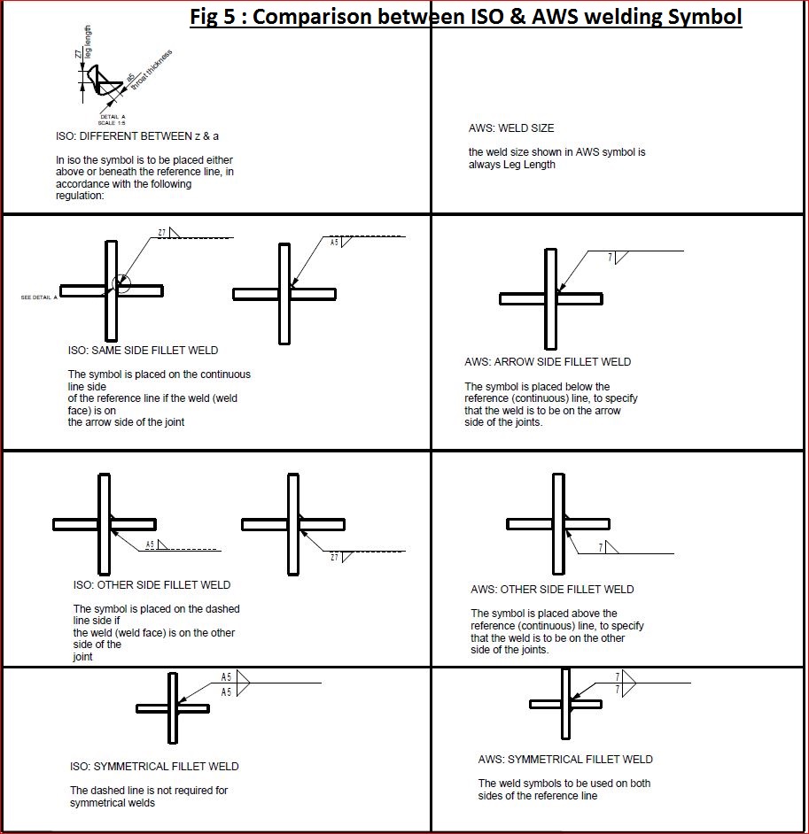
Sheet Metal Tolerance Standards welding symbol difference between ISO
A welding symbol is what you see above and contains the arrow, reference line, and tail. You can remove the tail if there's no information needed in it. You place a weld symbol on the reference line of a welding symbol to indicate what type of weld you require. 1. Reference Line
