Emergency Lighting Wiring Diagram alternator
️Emergency Light Remote Head Wiring Diagram Free Download Gambr.co
What's good guys, in this video i show the wiring, connection and testing of an emergency lighting circuit.You'll also see some tips and tricks and the curre.
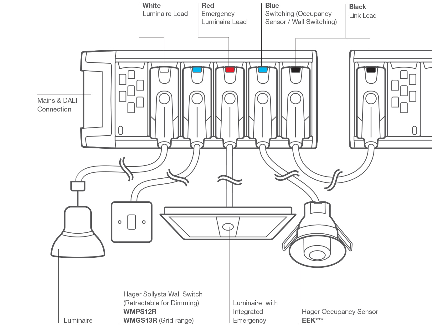
View Hager Light Switch Wiring Diagram Pictures udasami
Wiring diagrams for emergency lighting are used to plan and organize the wiring layout in a way that ensures the lighting system is properly installed and functions as it should. Without the correct wiring diagram for an emergency lighting system, it is impossible to ensure that everything will work as it should.
21 Lovely Emergency Light Key Switch Wiring Diagram
When it comes to emergency lighting, a wiring diagram is crucial as it helps electricians and contractors understand the layout and connection of all the emergency lights, exit signs, and power sources. This diagram acts as a roadmap for setting up the emergency lighting system, ensuring that everything is in place and functioning correctly..
Emergency Lights Wiring Diagram Collection
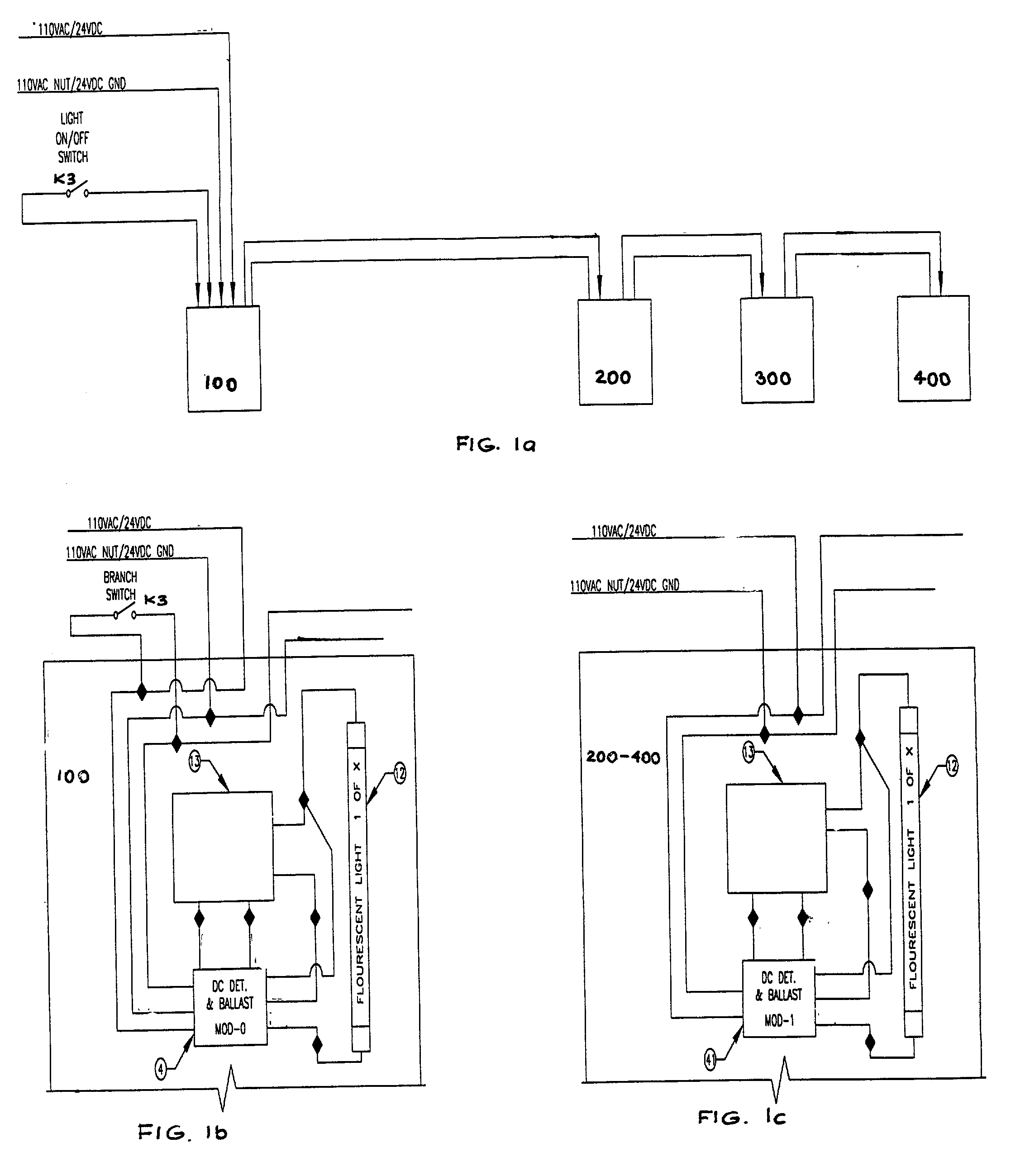
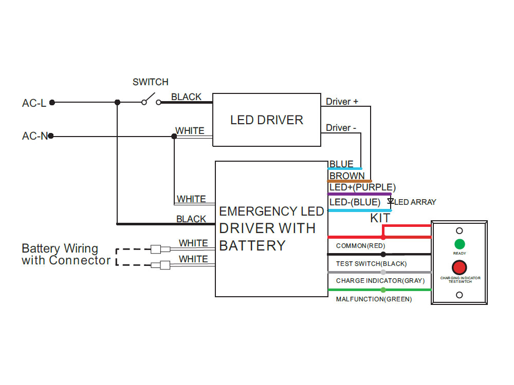
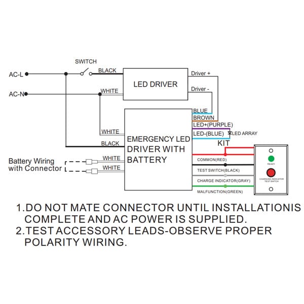
see wiring diagram - note 2 white common ballast hsg see note 3 under wiring diagram make connection for charge indicat or ballast cover emergency ballast lighting fixture models: wgc42fe c942fe nrg304be black, hot 1 120 or 277vac unswitched test switch/charge indicat or 4) see wiring diagram for required connections. swit ched unswit ched 120.

Emergency Lighting Wiring Diagram alternator
• Installation and wiring of emergency lighting systems • Commissioning and testing requirements • Certificates, log books and maintenance Compliance with BS 5266-1:2016 In the UK, it is a fire safety legislation requirement that emergency lighting

Wiring Diagram For Non Maintained Emergency Lighting
Case 1. Emergency-only lights on an emergency-only circuit The Case 1 arrangement is probably the simplest possible way to energize emergency lighting fixtures. A number of emergency-only fixtures are dedicated to providing the minimum illumination levels required by the NFPA 101, Life Safety Code, or local building codes.
Wiring For Emergency Lights
A crucial part of emergency lighting is the wiring diagram, which outlines how the system is connected and powered. The emergency lighting circuit wiring diagram shows the interconnection between various components such as emergency lights, battery backup system, control panel, switches, and power supply.

Wiring Diagram Emergency Exit Lights
Circuit Explanation We can divide this LED emergency light circuit into two parts; first part is used to drop down the 220v AC voltage into 8v regulated DC, with the help of Transformer and bridge rectifier. And second part consists of Relay and rechargeable battery, which is used to lighten the LEDs during power failure. Components:
Emergency Led Driver Wiring Diagram Wiring Diagram & Schemas
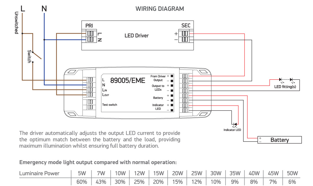
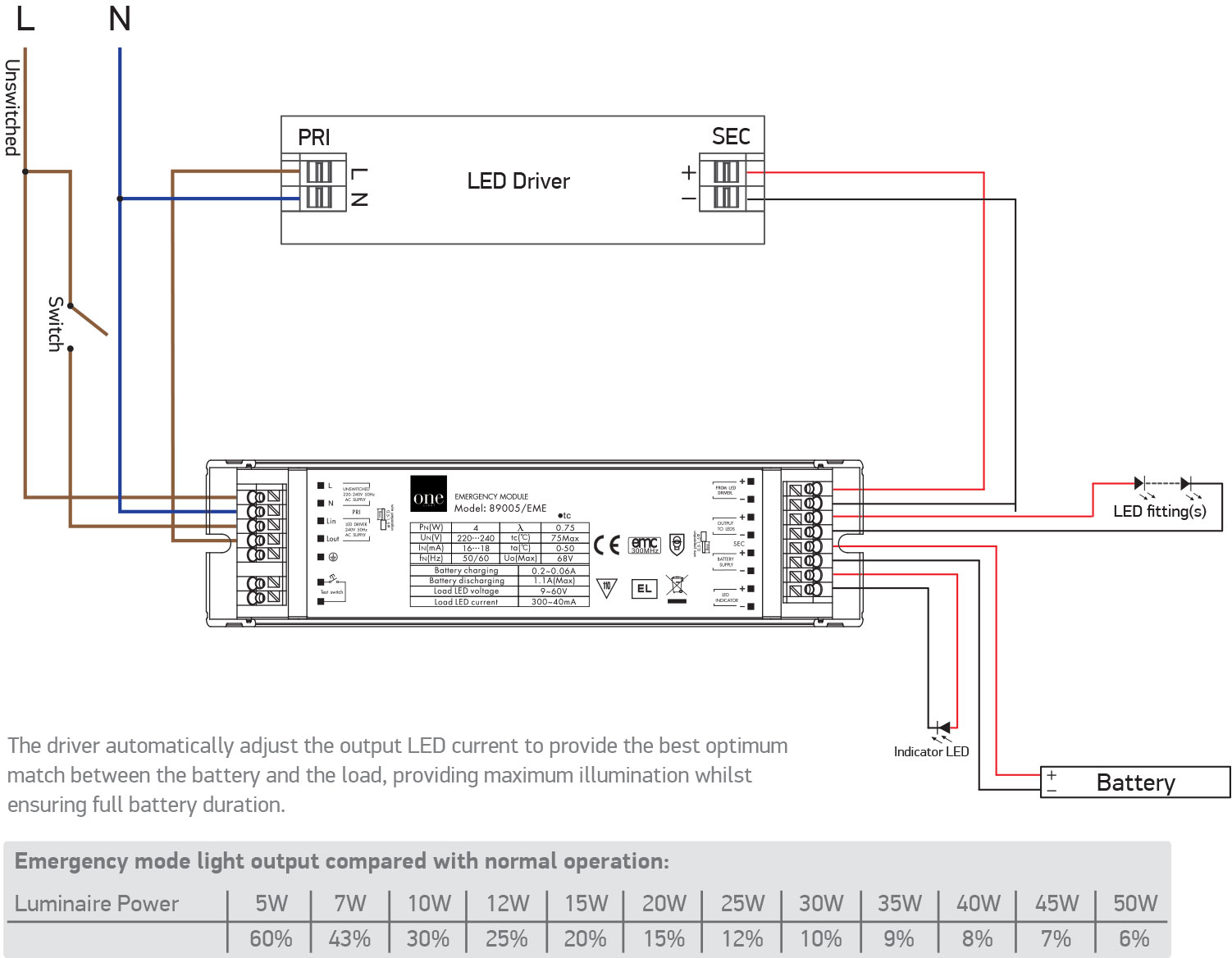
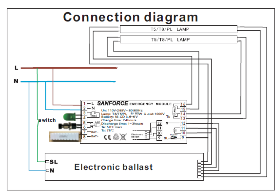
LED lndicator Battery - - - + SMD - LED lndicator Wiring for Maintained Mode: Switched Supply: Connect Switched Mains Supply Active from On/Off Switch to Switched Active terminal (Sw.A) Maintained Supply : Connect Hard Mains Supply Active to Un-Switched Active terminal (Un.Sw.A).

AUTOMATIC EMERGENCY LIGHT WIRING CONNECTION YouTube
Definition: An emergency light is used to automatically turn ON a lamp which is operated by a battery. It stops the user from being into a difficult situation because of unexpected darkness and helps the user to get access to make an instantaneous emergency light.
Emergency LED Driver 15 Watts Max 2548V Output 120277V Input Jen Lighting Wholesale
central emergency lighting power, suitable for traditional emergency power sources (diesel generator and slow transfer inverter backups) in addition to fast-transfer (FT) inverters or uninterruptible power systems (UPS).. Figure 01 - Example Wiring Diagram: rPP20 DS 24V ER EFP G2 Figure 02 - Example Wiring Diagram: nPP16 D ER EFP.
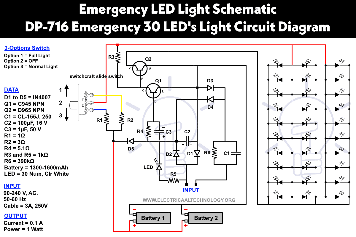
Emergency LED Light Circuit DP716 Rechargeable 30 LED's
A maintained emergency lighting wiring diagram is a graphical representation of the electrical system in a building or workplace. It shows the distribution of power from the main power source, through each of the lighting circuits, and out to the emergency lighting system.
Emergency Wiring Diagram
Ideas and Advice Safety & Emergency Lighting Guide Published 17 Jan 2023 Last Modified 29 Aug 2023 7 min Safety & Emergency Lighting Guide Understand all you need to know about emergency lighting regulations and discover how to test emergency lights. Topics Covered in this Guide What is Safety & Emergency Lighting?
Dual Lite Emergency Ballast Wiring Diagram
The wiring diagram for emergency lighting is a crucial part of the setup process and ensures that the lighting system works properly. In this article, we will discuss the basics of wiring diagrams for emergency lighting, including what they are, why they are important, and how to create one.
19 Best Emergency Exit Sign Wiring Diagram
WIRING DIAGRAMS EPC-1 20A EMERGENCY HOT #5 BLUE EMERGENCY PANEL OR INVERTER #6 YELLOW Emergency Light #7 WHITE/BLUE EMERGENCY NEUTRAL Note: Emergency Light is also called N/E or Normal/Emergency Light EMERGENCY POWER TEST SWITCH UTILITY POWER 20A #1 BLACK 120V REGULAR HOT #2 ORANGE 277V #3 RED * REGULAR PANEL Regular Light (optional)
Emergency Led Driver Wiring Diagram Wiring Diagram & Schemas
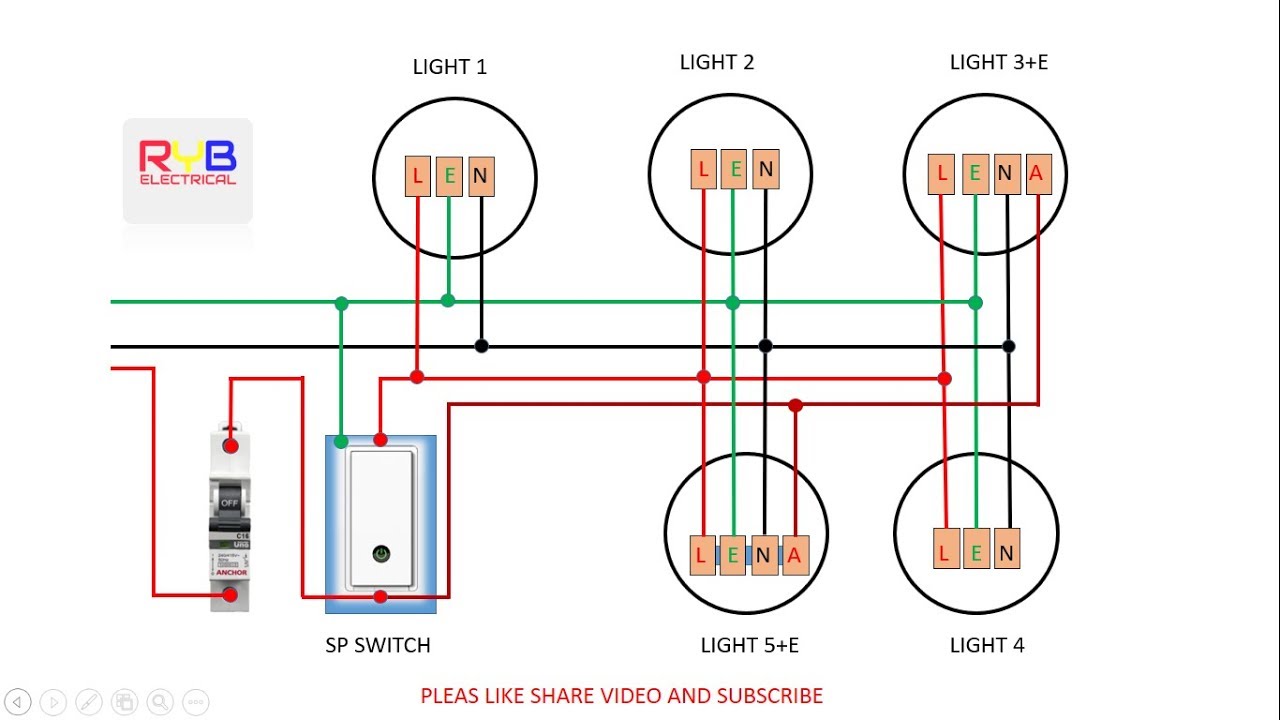
The diagram you use should match the type of emergency lighting system you plan to install. For example, if you are wiring a system with single-pole lights, you'll need a different diagram than if you're wiring a system with double-pole lights.
