Garage Door Sensor Wiring Schematic
Garage Door Opener Wiring Diagram Cadician's Blog
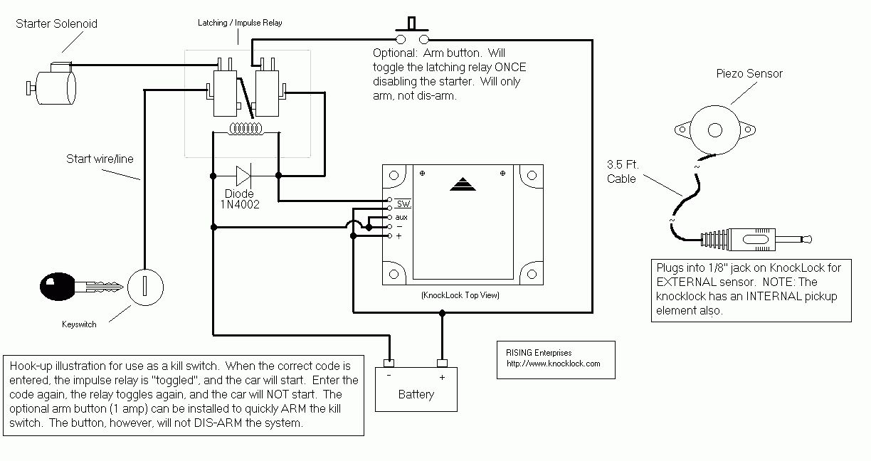
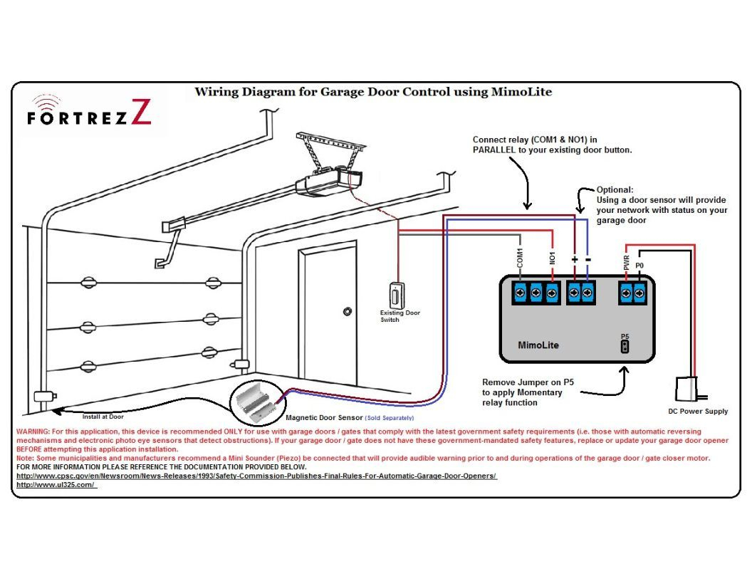
A garage door opener wire diagram visually represents the electrical connections and wiring in your opener's operation. It's a valuable resource for identifying and understanding the components, wiring paths, and electrical connections within the system. Components of a Garage Door Opener Wire Diagram
Chamberlain Garage Door Opener Wiring Diagram Cadician's Blog
Using a small screwdriver, paper clip or similar tool, set the DIP switch to any sequence you like. Locate the DIP switch on the remote. Using the same tool, set the switch to match the sequence.
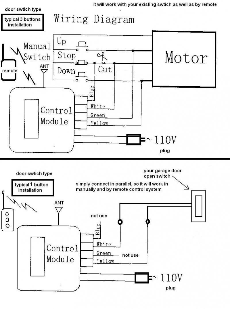
3 Button Garage Door Wiring Diagram For Control Wiring Diagram
Follow these steps: Turn off the power to the garage door opener at the circuit breaker. Locate the power input terminals on the opener's main control panel. These terminals are typically labeled "Power" or "AC Power". Strip the insulation off the end of the power wires using wire cutters/strippers.

Concept 20 of Wiring A Craftsman Garage Door Opener blogtelanjang
Openers with Screw Terminals. Strip 7/16-inch of insulation from each solid-white and white-with-black-stripe wire on both sensors. Twist together the two white-with-black-stripe wires from both sensors. Twist together the two solid-white wires from both sensors. Connect the two white-with-black-stripe wires to screw terminal 3 on the motor unit.

Genie Garage Door Sensor Wiring Schematic
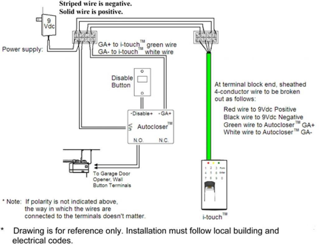
The wiring diagram Genie garage door opener consists of the following components: a power supply, opener switch, safety beam, opener wiring, wall control, and doorbell wire. Each of these components is responsible for a different task and must be connected properly in order for the opener to function correctly.

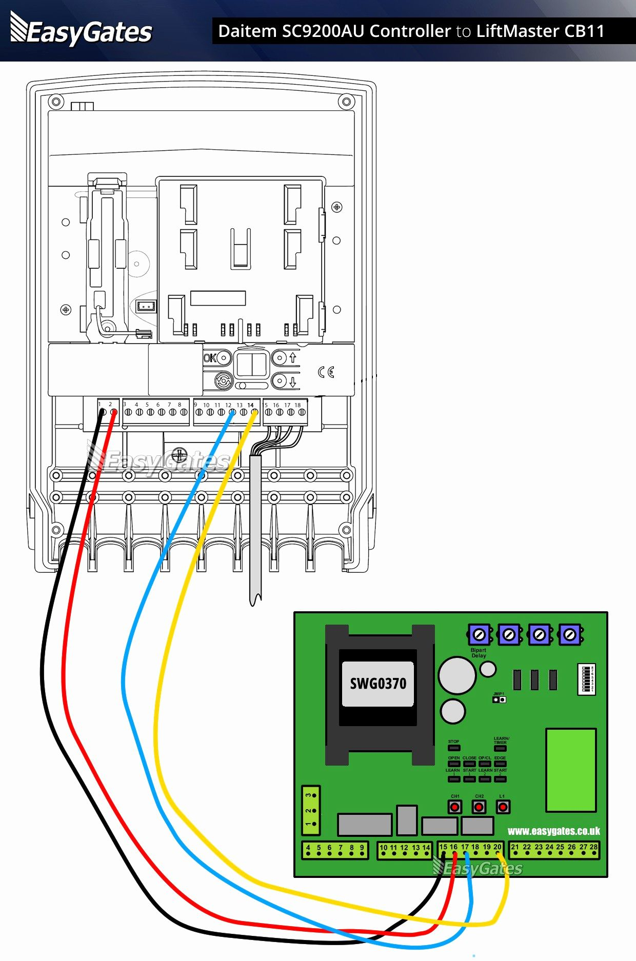
Wiring Diagram For Liftmaster Garage Door Opener Free Wiring Diagram
How to wire a garage door opener is easy and simple. I demonstrate how to install a Chamberlain MyQ garage door opener specifically focusing on the wiring. B.
Liftmaster Garage Door Opener Wiring Diagram Dandk Organizer
How to Wire the Door Control for a Garage Door Opener Determine if you have a Security + 2.0 opener and if you have the plug-in terminals or the screw terminals on your unit. Use a 2 conductor 22 gauge bell wire for this task. For Security + 2.0 models

Liftmaster Garage Door Opener Wiring Diagram Dandk Organizer
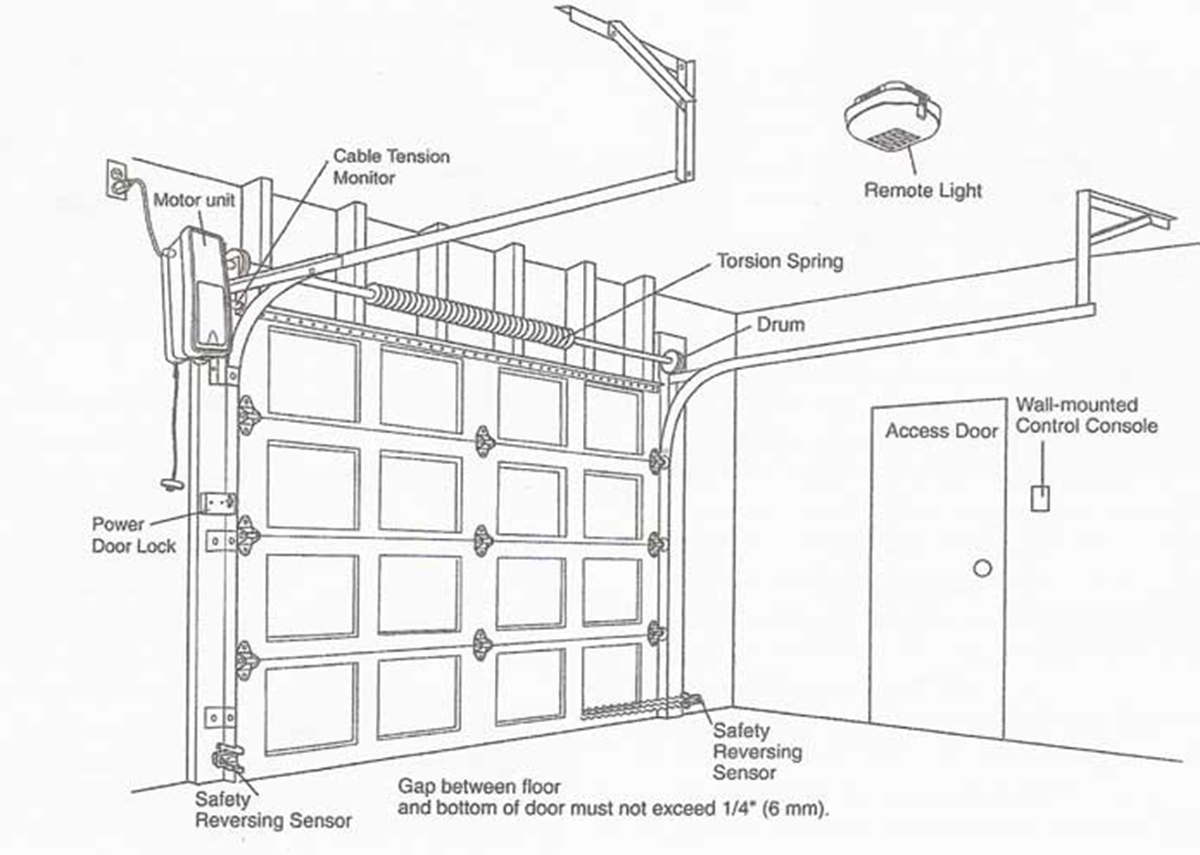
Safety Sensors Modern garage door openers are equipped with safety sensors as a crucial safety feature. These sensors are typically mounted near the bottom of the garage door, on each side of the opening. The safety sensors emit an infrared beam that detects any obstruction in the path of the closing door.

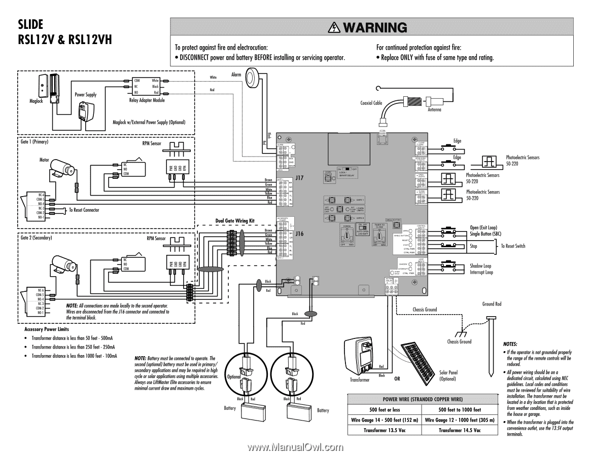
Liftmaster Garage Door Opener Wiring Schematic Free Wiring Diagram
Garage wiring diagrams outline the various electrical circuits and components needed to power lighting, receptacles, garage door openers, and other electrical devices in a garage.

Craftsman Garage Door Opener Wiring Diagram Garage Doors
The Genie garage door opener wiring diagram shows you how to connect the control board to the circuit. To begin, locate the orange tabs on the DCM. Once you have located these, you can connect the wiring harness to the wall control or directly to the opener. The terminal screws will be located on the back of the opener head.
Chamberlain Garage Door Opener Wiring Diagram Cadician's Blog
How to wire a three screw terminal garage door opener The back of the motor has 3 screw terminals numbered 1, 2, & 3. This is where the door control and safety sensors are wired. To wire the door control Attach the striped red/white wire under screw terminal 1. Attach the solid white wire under screw terminal 2.
Garage Door Sensor Wiring Schematic
The Significance of Wiring Diagrams Garage Door Opener Safety First Garage doors are heavy, and an improperly installed opener poses safety risks to people and property. The wiring diagram ensures proper connection and functioning of safety features like auto-reverse, infrared sensors, and emergency release.

Electric Garage Doors Wiring Diagrams
A garage door opener schematic diagram is a detailed representation of the electrical components and connections that make up the mechanism responsible for opening and closing the garage door. It may seem like a mundane concept, but the design and functionality of these diagrams are crucial to the smooth operation of your garage door.
Liftmaster Garage Door Opener Schematic
Before You Begin Before you start wiring your Chamberlain garage door opener, it's important to gather all the necessary tools and materials. Here's what you'll need: Chamberlain garage door opener Wiring cables Wire strippers Screwdriver Drill and drill bits Wire nuts Tape measure Electrical tape Understanding the Wiring Requirements
Liftmaster Garage Door Opener Wiring Diagram Bios Pics
A Raynor garage door opener wiring diagram is a helpful tool that gives detailed instructions on how to properly wire the system. It guides you through the installation process, step by step, ensuring that the components are correctly connected and securely fastened. With the help of a good wiring diagram, even novice DIYers can successfully.

Chamberlain Liftmaster Garage Door Opener Wiring Diagram Dandk Organizer
Locate the power source Identifying the power source is an essential step in wiring your LiftMaster garage door opener. Most garage doors have an existing power outlet nearby, while others may require direct wiring to the circuit breaker. Follow these steps to locate the power source:
