Flow Control Schematic Symbol
hydraulic flow meter symbol Willia Gooch
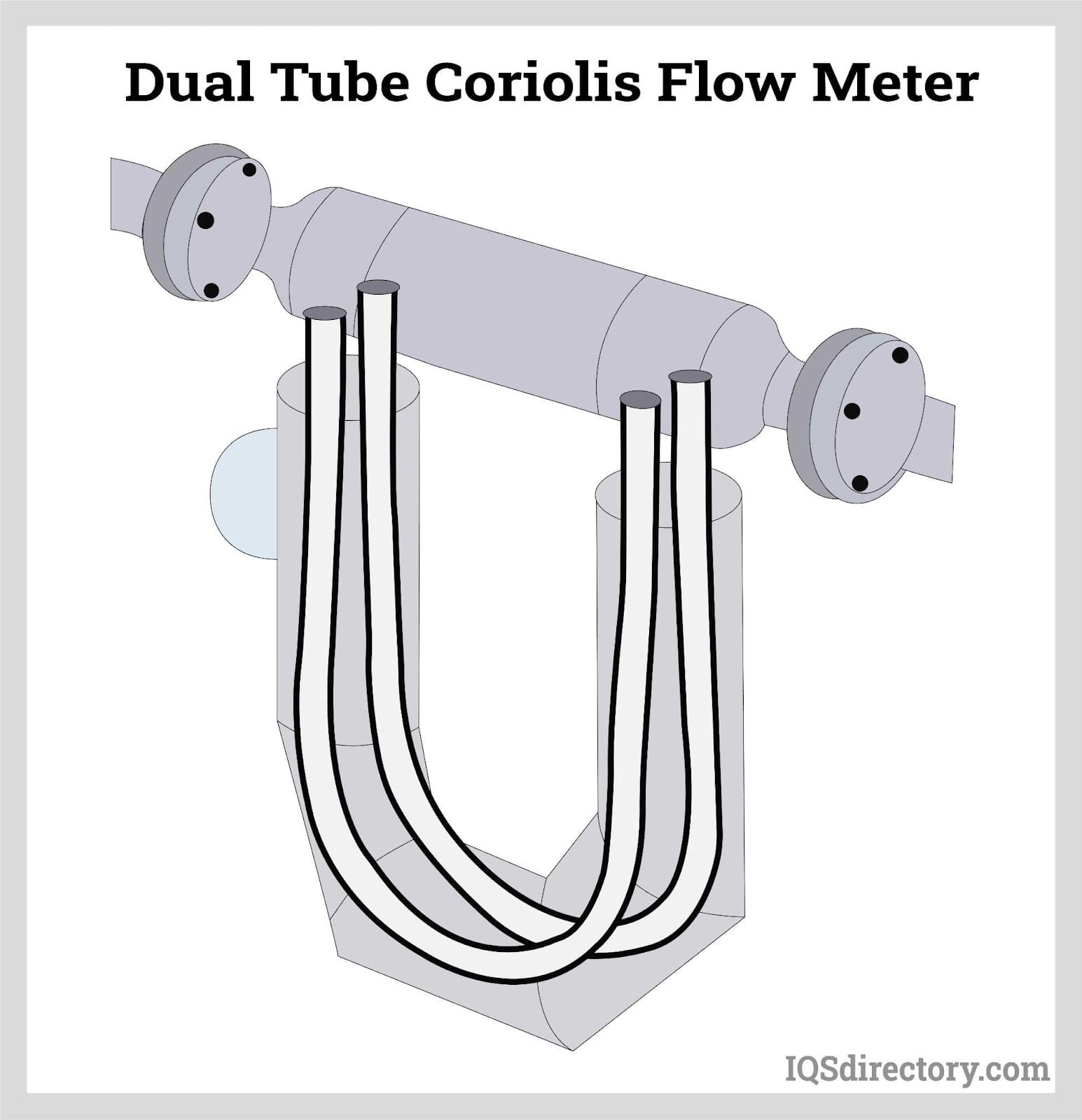
Coriolis Flow meter symbol. In a P&ID drawing is: Conclusion. A Coriolis flow meter is a special kind of Mass flow meter that works on Coriolis force. This is also called an Inertial flow meter as oscillation and phase shift occur because of the inertial motion of fluid in the tube. Some of the bullet points of the Coriolis flow meter is:
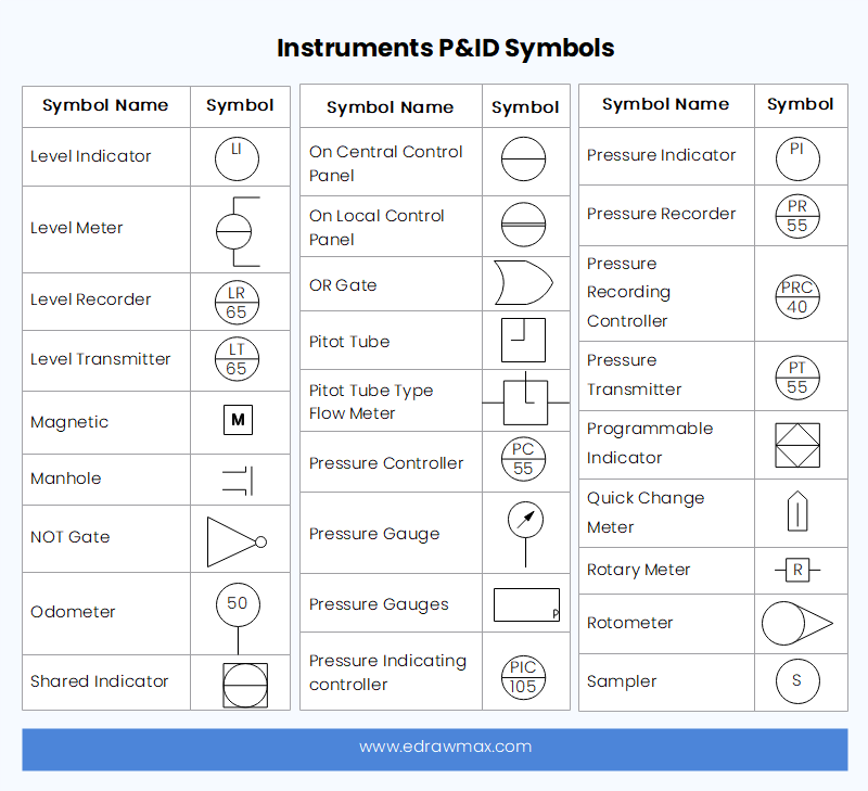
P&ID Symbols and Meanings EdrawMax Online
The symbols used in piping and Instrumentation diagrams or drawings are many and varied. I have dealt with some of these symbols before but here I have given a comprehensive list of the common P&ID symbols of process equipment such as valves, flowmeters, piping line connections, and much more. Go through them and familiarize yourself with them.
Flow meter cad symbol
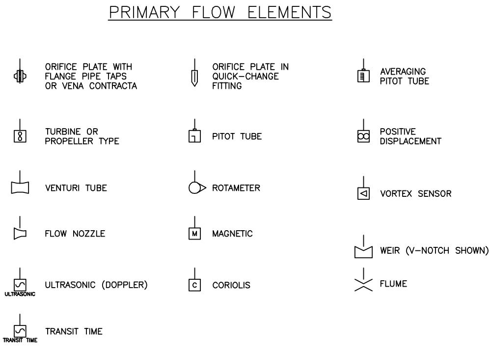
A flow diagram is a simple illustration that uses process symbols to describe the primary flow path through the production equipment. It provides a quick snapshot of the operating unit and includes all primary equipment and piping symbols that can be used to trace the flow of the well stream through the equipment.

Learn P Id Diagram Basics Symbols To Read P Id Diagrams Easily My XXX
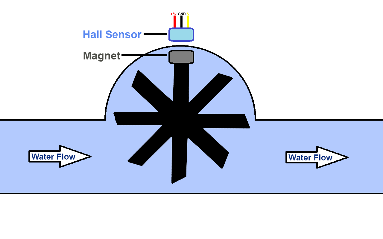
In engineering contexts, the volumetric flow rate is usually given the symbol , and the mass flow rate, the symbol ˙. For a fluid. Turbine meters are less accurate than displacement and jet meters at low flow rates, but the measuring element does not occupy or severely restrict the entire path of flow. The flow direction is generally.

Innere Geige Regenerativ mass flow meter symbol äußerst ethnisch maximal
Here is a list of PID symbols pertaining to Instrumentation. Analyser Transmitter. AND Gate. Averaging Pitot Tube. Behind Control. Behind Local Control. Computer. Computer Indicator. Coriolis Flow Sensor.
Flow, flowmeter, fluid, measurement, movement icon Download on Iconfinder
P&ID SYMBOLOGY. Piping and Instrumentation Diagram, P&IDs, are detailed drawings used in the process industry that depict piping and process equipment, instrumentation and control devices along with safety systems in place that ensure the process remains running in a safe operational state. Applicable to the complete process life cycle, they.
Coriolis Flow Meter Symbol
🔴 Link to Entire course on Udemy https://www.udemy.com/course/how-to-read-pids-piping-instrumentation-diagrams-symbols/?couponCode=2DF8267E1EB86BD1882CDiffe.
Oval Gear Flowmeter Working and Installation Guide
P&ID is an abbreviation meaning ' Piping and Instrumentation Diagram '. Piping and Instrumentation Diagrams are graphical representations of a process system. These are fundamental to every standardized engineering project. These two-dimensional diagrams function as a blueprint for the engineering system's design.

P&ID symbols for level and flow measurement devices Industrial
- 3 - ANSI/ISA-5.1-2009 Preface (informative) This preface is included for information purposes and is not part of ANSI/ISA-5.1-2009. This standard has been prepared as part of the service of ISA, The International Society of Automation,
Flow meter cad symbol
The flow transducer is mounted atop the symbol for a flow meter. All mechanical measurement symbols employ a circle, such as with the pressure gauge or thermometer, and you must imagine that fluid passes horizontally through the convex shapes where its rate of flow is measured. In reality, this can take place via myriad methods, once again.

Flow Meter Illustrations, RoyaltyFree Vector Graphics & Clip Art iStock
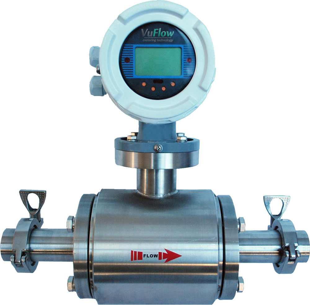
Ultrasonic flowmeters. As the name suggests, ultrasound is used to calculate the velocity of a liquid. The flowmeter then uses the value of the measured velocity and the size of the tube to calculate the volumetric flow of the liquid. The velocity of the liquid is measured in two ways: The first is based on the principle of the Doppler effect.

DN600 flow meter symbolin Flow Meters from Tools on
The most popular symbols are actuators, equipment, flow elements, instrumentat. What are P&ID symbols? P and ID symbols are used in engineering system designs to represent process working and sequence.. Common instrumentation symbols are meters, transmitters, sensors, indicators, and other measurements and recordings. Click to download and.

Common P&ID symbols used in Developing Instrumentation Diagrams
Meter-out: - control of the flow rate at the outlet side of the actuator. Bleed-off: - delivering partial pump output to the tank; Check Valve. Check valve allows the fluid to pass only in one direction and restricts flow in the opposite direction. Note: Arrow is not part of the symbol. It represents the direction in which fluid can flow

Flow Control Schematic Symbol
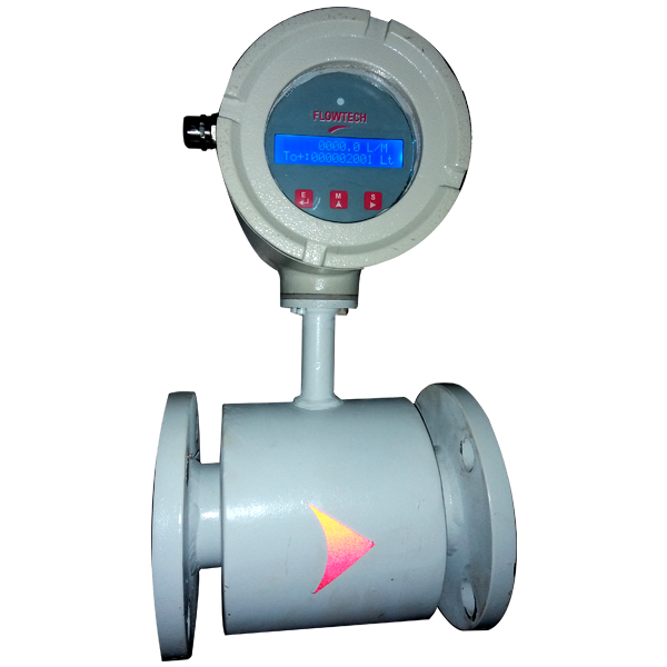
Hydraulic flow meter symbol. The symbol shows a fluid flow meter with digital display. For different displays or electrical communication systems, the flow meter symbol would remain the same but the symbol in the square connecting box would change. The bottom symbol shows how to measure flow in both directions with a single flow meter.

DN50 flow meter symbolin Flow Meters from Tools on
A set of standardized P&ID symbols is used by process engineers to draft such diagrams. P&ID symbols exist for all major components and lines, such as valves, vessels, instruments, pumps, compressors, and towers. The ISA S5.1, ISO 10628, and BS 5070 cover the standardization of P&ID symbols and guide process engineers in their plant design.
Water Flow Meter Symbol Tatoo Writing Sex Video
Hydraulics: Graphic symbols Pumps, motors, cylinders and equipment p1 p2 P P S M1 M2 P T Cooler with liquid coolant. Flow indicator Flow meter Tachometer Torque meter Accumulator with accumulator safety block • Shut off device • Equipment against excessive pressure • Discharge device
